Note: The following was written about 0.18. We’re now on 0.20 and some of these issues are being addressed. It is far more usable than when this guide was written. There is a project to significantly re-write FreeCAD for a version 1.x which is out now. However it has some early bugs. It is probably the best place to start and will be the future of the platform.
TL;DR:
The sections of the article about CAD is still useful and includes decent information, so I suggest a read if you’re interested in that.
After using FreeCAD some time, I’ve decided that while it’s very cool for a free program, for someone needing to get things done with parametrics and standards (threads, dimensioning, drawings, etc.) it simply isn’t there yet. So I’ve abandoned the guide to updating it’s interface. There’s so much to change, hopefully there will be a way to export and import configurations. The FreeCAD project could use help from a major sponsor, like CERN did with KiCAD, to focus development and resolve issues.
Here are the relevant issues:
- Variables driven parametric features are difficult to setup and use.
- Interface is perplexing and inconsistent.
- Too many conflicting methods of doing ‘X’, none that offer full solutions.
- Poor syncing between ‘workbenches’, ie parameters, part and drawing.
- Missing basic features like fillets between a curve and straight line, padding (extruding) multiple or split bodies from a single sketch, non-linear feature updates and modeled threads.
- Sketch constraint solver is great with basic geometry but suffers with advanced geometry like ellipses.
Index
- L’Histoire (The History)
- Parametric (I’ll take n. n=2)
- From Install to Usable (FreakCAD)
- What’s That? Guide to FreeCAD’s Interface
- Start Page
The CAD market exploded sometime after the recession. I suspect it had something to do with all those folks buying FDM machines (‘3D Printers’) and then needing a way to make things to fixed dimensions.
L’Histoire
There used to be two worlds of CAD. 2D Drawing/Drafting and 3D Engineering Modeling. Then the architects got hip to computers and added a bunch of building-related variations. Next the world of 3D modeling (film CG, simulation, video games, etc) realized that modeling things designed by engineers is easier in CAD. That muddied the market a bit. One universal truth about 3D CAD was that it was expensive and required high-end hardware to run.
In the mid to late 00’s there were only a few options for parametric 3D CAD: SolidWorks, AutoCAD, and ProEngineer & NX (less common in US). Autodesk came out with Inventor which gave many an alternative to SolidWorks. That’s the professional world, which was pretty much the only world. Well, there were one or two very basic 2D CAD-style drawing tools in Linux.
In the last few years (2012-on) there is an expansion and stratification of the market. Pretty much every CAD producer makes three levels of product targeted and student/consumer to multi-national corporations. There are also a couple pieces of software that migrated into the parametric CAD world like Rhino (with Grasshopper) and Blender (less so).
I’m not sure whether it was the chicken or the egg but Autodesk Fusion 360 came out around the same time as OnShape. Both eventually got attention by suckering incentivizing new users by offering free versions.
I tried OnShape first because I literally couldn’t find the right page/button on the AutoDEsk site for Fusion360, and I thought it was just a CAD file viewer. Autodesk still has one of the worst website to actually find anything, Adobe and Microsoft are almost as bad. OnShape was, uhh, useless to me. Slow (because of its remote execution) and had a non-existent feature set and frustrating sketch tools. On top of that there were a lot of restrictions on the files (for the free version). It’s a totally cloud software that works in a browser so it doesn’t work at all with even the smallest interruption in service. Of course once you got out of the free/demo mode it got pricey fast.
A little later I started playing with Fusion 360 (I believe after watching a YouTube video, probably from NYC-CNC/John Saunders). It’s free version is actually free for hobbyists and low-income businesses. It’s a ‘cloudy’ program. The whole thing runs locally and it can use real files (with some headaches). Overall, it’s a very capable piece of software. It is however in an almost permanent beta. Every time I open it the software updates and something works slightly differently than before. It also vomits a mess of files all over your main hard-drive. Probably the biggest selling point was the inclusion of CAM software (basically HSMWorks). What they’ve realized is that there is a huge potential user base of people making things without a long engineering and manufacturing toolchain that need to go from idea to CNC with as few steps as possible. It has issues though and for me the eventual cost was going to look like a questionable value compared to other options. You also have the subscription model problem. How do I know this software will be around 3 years from now? Will I even be able to open the files I made?
The quest was on for a decent CAD that I could grow into. I spent a lot of time looking at Rhino 6. It’s not so much a traditional parametric CAD as it is a crazy powerful solid modeling tool that has been assaulted by architects and designers to include advanced algorithmic modeling tools. SolidWorks was getting a second look, but oh my! the price! Another option is Alibre, which is slightly more affordable than Solidworks and unlike Fusion360 you own the software and can operate entirely off-line if you wish. I tried Alibre, it does some things well but variables-driven parametrics is a very weak point. FreeCAD is actually far better at that aspect.
I’m still not sure I found that CAD.
Parametric
There’s a lot of focus here on parametric design and features. So what exactly do I mean by that? The simple definition is that any aspect of the design can be updated without breaking the model. There are certainly limitations to this. You can’t design something with 2x4s and then update a hole in the model to have a 4 in hole. Actually, a true parametric CAD would allow you to define limits for the input of dimensions to prevent such a circumstance.
Most parametric implementations use something akin to a spreadsheet or table to enter variables. How this is implemented varies and many packages carry limitations on what can be controlled or how the data is entered. Parametric is not feature history, timelines, etc. It does however require the software to understand and order of operations and be able to recalculate the model.
For someone designing a one-off part to go to a laser cutter, parametric may be a hassle. It’s just as easy to go to a sketch dimension or use a transform tool to tweak the part.
There are two primary use-cases for parametrics. The first is when you need to update some aspects in the future without breaking the design. What if you change a 3/8-16 fastener to a M10x1.5 later on down the road? Does the hole go off-center? Will your material thickness provide the same thread engagement? Is a nearby corner radius still concentric? The second case is when your are going to iterate versions of a design. Imagine a beam with a hole centered along it’s length. If you increase the length by 1.3x you still want that hole centered. Now add a complex hole and notch pattern inset by a fixed amount for a range of lengths. Say 2in for 1-2ft, 3in for 2-4ft and 5in for 4+ft. That would require a lot of editing with a normal model but could require one or two edits in a fully parametrized model. Imagine a different case where you have a part that may be cast or milled. In the cast part you’ll need to add draft angles, and account for shrinkage. In the milled model you may leave more material in the pockets to reduce machining. What if you could switch between them with a single click? Most CAD software requires more than that but there are some clever ways to cut it to a minimum.
There are two main implementations of parametrics in CAD software: references and variables. They both do the same thing but work differently for the user. Let’s say you have a bar that needs a threaded hole drilled, tapped and countersunk in the center in both length and width. The bar is 5in long and .5in wide. You could sketch that with dimensions, extrude the shape of the bar and then select the face to place the hole and set the sketch dimensions to 1/2 of the length and width of the referenced face. This makes a parametric hole that will stay centered relative to the face it’s on if the bar is resized later. Another option is to externalize those numbers and drop references in. That’s a blend of the methods. The third method is to create a variable for each dimension needed and do all of the math outside of the model then feed those variables to each dimension. Rather than directly referencing the face of the bar for the hole sketch, we can use an offset from the base plane.
It all gets you to the same place but the limitations and workflow of the software suggest the best method for any given circumstance. If you are just ‘thinking in the computer’ then I’d just go and get the idea fleshed out. After you’ve tackled the problems then you can rebuild in place or start over with a fresh model clearly designing your parameters. You’ll also have a pretty good reference for your dimensions.
A note on Fusion 360 and FreeCAD parametrics
Fusion is good about doing reference parameters. It makes selecting elements outside the body you are working on [too] easy. Fusion also creates automatic entries for most elements like sketch and feature dimensions. It however has two incredibly annoying problems:
- You can’t have the parameters window open and do anything with the model or modelling interface. You literally have to open and close the window to do anything in the model view.
- You can’t convert/copy an existing automatically created parameter into a user-defined model parameter. Well, you can re-name parameters, so that’s good enough.
- There’s no efficient way to import/export/externally reference parameters, like an Excel sheet.
FreeCAD presents a whole separate set of problems. The first is to understand that the software is being developed by a large pool of mostly volunteer coders. Unlike most professional software the FreeCAD community expects its users to also understand some of the software design for limitations/features. This is becoming less true as the code gets more robust.
As of the most recent stable release (0.18) the ability to use ‘equations’ in dimension entries is available almost(!) everywhere you’d need it. There is a somewhat robust presentation of extant parameters that can be selected from within this tool and its formula handling is functional.
The variable entry is done through a “Spreadsheet” which is somewhat flexible in its ability to have hard-coded formulas. It doesn’t have a unified system for displaying and entering these variables though. That makes the process of creating these parameters somewhat inefficient and tedious.
From Install to Usable
The current stable version of FreeCAD is 0.18. It’s available on all OSes, however there are issues with installing on Windows vs Linux. A number of utilities require external dependencies that are more difficult to get running in Windows. Some of those are normal menu items that throw an error because the dependencies are missing.
This guide is not supposed to be a complete guide to every feature or modelling. I’ll mostly cover the things I think are actually useful in replicating the workflow of Fusion.
What’s That? Guide to FreeCAD’s Interface
The most important thing to understand in FreeCAD is the concept of ‘Workbenches’. These are just preset toolbars designed around specific tasks. OK, there is more to it on the development side but for the user you can just think of the Workbench selector as a toolbar auto changer.
Start Menu
When you open you’ll get a goofy start menu.
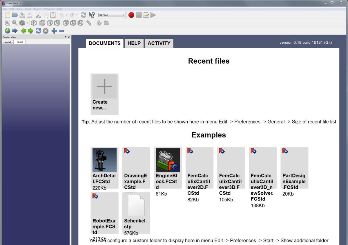
If you like this menu, at least get rid of all the example files and replace it with more recent files.
Edit > Preferences Menu > General > Main Window > Size of recent file list: 4 or more.

Also:
Edit > Preferences Menu > Start > Contents > Show examples folders contents: off.